

Hi! As promised, here's my progress so far. This post will also be the loose format of how I want to post these in the future. I intend to have four sections: what I've been up to, what new developments have come up, and what I have planned next, and if there's any immediate opportunities to help. I also want these to be written casually so I don't have to agonize over them, and so that they're fully readable by technically experienced folks but also skimmable with occasional tl;drs for curious but not electronics literate onlookers.
What I've been up to
In ultra brief summary, my last week on this project was giving up on the LM334, which is a lovely chip if you want a precision low-amperage source (seriously I was getting stable single microamp precision), but it just has too many quirks for use as an on the fly adjustable current source. I've since committed to a dual opamp design I found on some blog somewhere and I haven't looked back, because it seems to work perfectly. I designed a circuit, simulated it, it worked swimmingly, I laid it out on a PCB, ordered it, and ordered parts to build it out.
Here's the blog post - I went with the "Two Op-Amp Topology". It's actually sick as hell. Here's my implementation of it in SPICE:
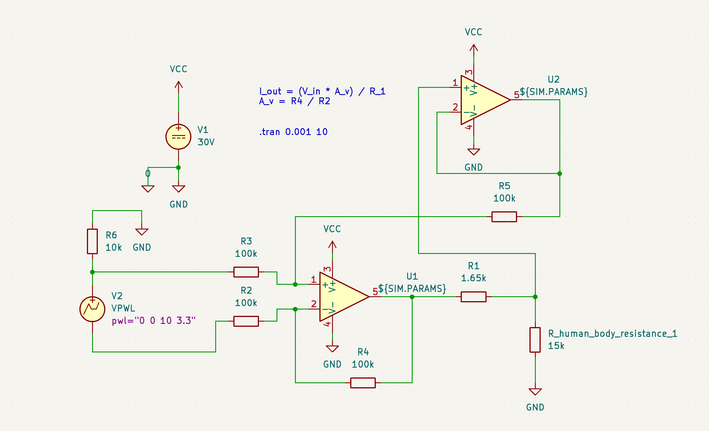
Something I'm really adamant about on in regards to safety (a core objective) is that this needs to have hard limits on both current and voltage. I've been able to design this in in the simulation, see:
It's hard to tell exactly what's going on here if you don't know how to read circuit diagrams and also know how I set this up, but essentially, I'm varying the simulated human body resistance and looking for it to behave the same way as I do so. Even if the device can drive the amps into you by current and voltage availability alone, it's hard capped at 2 mA, with the voltage limit imposed by whatever voltage you give the opamp and the current limit imposed by (basically) the resistance of R1. (More technically, this is a voltage controlled current source, and the voltage applied to V_current_set is divided by the resistance of R1 for the value of the current sourced from U1A.) All bodies are not the same resistivity, all parts of the same body are not the same resistivity, and even the same part of the same body is not always going to be the same resistivity. It's important that the administered current and voltage don't vary based on user, body part, and et cetera. This is an important safety and performance feature that most other DIYers I've seen have omitted. This is exactly what I was hoping to see this design do and it nailed it.
So, I drew up the circuit, routed the PCB, and with that, we're here:
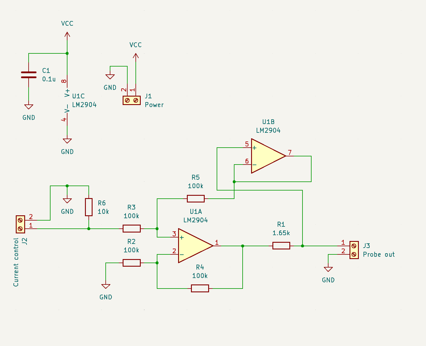
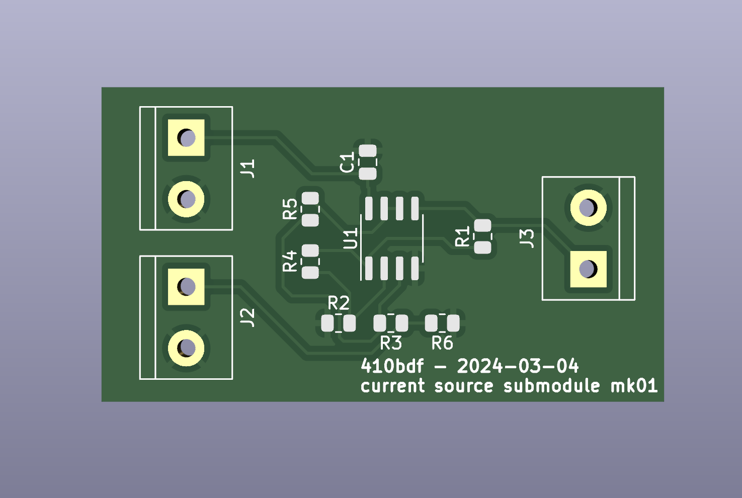
It comes in the mail next week! Thanks to @lapis and @macerated_baby_presidents for the JLCPCB rec, I didn't get a populated board, I wanna build it myself, but their service has been nice so far and I look forward to ordering a populated board from them soon to test accessibility! I left off test points, status LEDs, and some other stuff. That's okay. I'll do better next time. :comfy: The important thing is that this circuit is the circuit I'm rolling into 1.0.
Non-technical tl;dr: This is the circuit that takes in a normal power source and conditions it into the correct amount of power, specifically voltage and current, to kill hair follicles in a safe and controllable fashion.
New developments
I decided to give up on microcontrollers. 💔 For now.
Adding a microcontroller adds a lot of pros, and a lot of cons. The upshots are that it really makes this into something cool, something with flipper zero vibes - I'd be able to add a splash screen with graphics and I'd be able to explicitly list voltage/current/pulse time numbers on a display, I'd be able to shift a number of changes into firmware over hardware, meaning quicker debugging, and more. The downside though, is that I'd likely be requiring end users to flash a firmware build (not accessible, breaking one of the core 3 objectives), I'd be dealing with a data bus like SPI to get the screen to run, which is a pain to debug, and I'd be opening myself up to feature creep. I decided to axe it for now and just do everything by knobs with no screen to be able to get y'all a working basic finished project sooner. ❤️🩹
Next up
My availability is somewhat limited for the next week, but I want to at least build out this board and test it on the bench to make sure it actually applies the current I designed it to. While I'm waiting for this, I can start to design the other parts of this circuit. I have the power conditioning designed, next up I need to design the following, roughly in this order:
- instead of just loose inputs I put voltages on, I want to make knobs that set the amperage.
- I need to add timing circuitry so that instead of just an on/off, the user pushes a button and the device outputs current for an amount of time configured by a second knob.
- I need to add power conditioning, so that a 9V battery, an 18650, or something like it can be boosted up to generate the voltage required to drive the current required to smoke ur hairs.
- Fit and finish. Oh, and all of the activation switch and applicator probe everything.
I can probably design 1 and 2 in the next week. I definitely won't be able to actually build and test them until late next week, but now that I'm getting better at SPICE, I can simulate them, which will give me the (probably ill-founded) confidence to order boards without testing anything on the bench first. Likely no updates until mid next week due to this.
Any ways to help?
First of all, ask to be put on the tag list if you want updates! Knowing there are other real life human beings who think this is cool helps me a lot. Besides that, no electronics help at the moment, I don't have enough done to have any shared work to propose. Soon, I'll start thinking about the current probe, and I'll need help thinking about that. Besides that though, just get hype and if you know anyone who knows anything about electrolysis hair removal, let them know about this so they can be here for discussions if they want to be!
I'll see y'all some time next week for the next update. Thursday of next week or earlier. It's in my calendar. Bye!
tag list: @ComradeEd@lemmygrad.ml, @raven@hexbear.net, @Wake@hexbear.net, @BountifulEggnog@hexbear.net, let me know below if you want to be added or removed!
add me to the ping! this is cool!
I've got enough knowledge to populate and likely troubleshoot a board like this but not enough to tell you anything you don't already know! I'd totally build one and test it out or help manufacture it or whatever if that becomes necessary
oh also jlcpcb is probably a faster and more capable vendor esp if you might eventually want other services but I've also used OSHPark with decent results. honestly tho the big players may have the economies of scale to beat them on speed and price. and probably exotic board types too i just like the purple solder mask tbh lol
OSHpark is so expensive and doesn't do assembly but I will say that they offer a very easy "click button get PCB" distribution solution via the sharing center. I've used that before, on some board that the author lost the source files for.
yeah it can't beat any of the overseas ones on price. But for the little projects I've used it for it's been cheap enough that I didn't care it wasn't technically "a good deal". For bigger PCBs that may be different. It was pretty fast (maybe I got lucky?) but not really better than jlc on that either even in the best case
idk why I have any loyalty to it... I mean I don't really but I've only ordered pcbs a handful of times and I think the first one was one of those links you mention. someone on hackaday made a Pi Zero GPIO to VGA adapter board that I wanted to try (worked astonishingly well tbh even with "best I could find at the surplus store" through hole resistors)
I do like the purple and gold tho, and I've heard their quality is better in some ways that I almost certainly don't need