
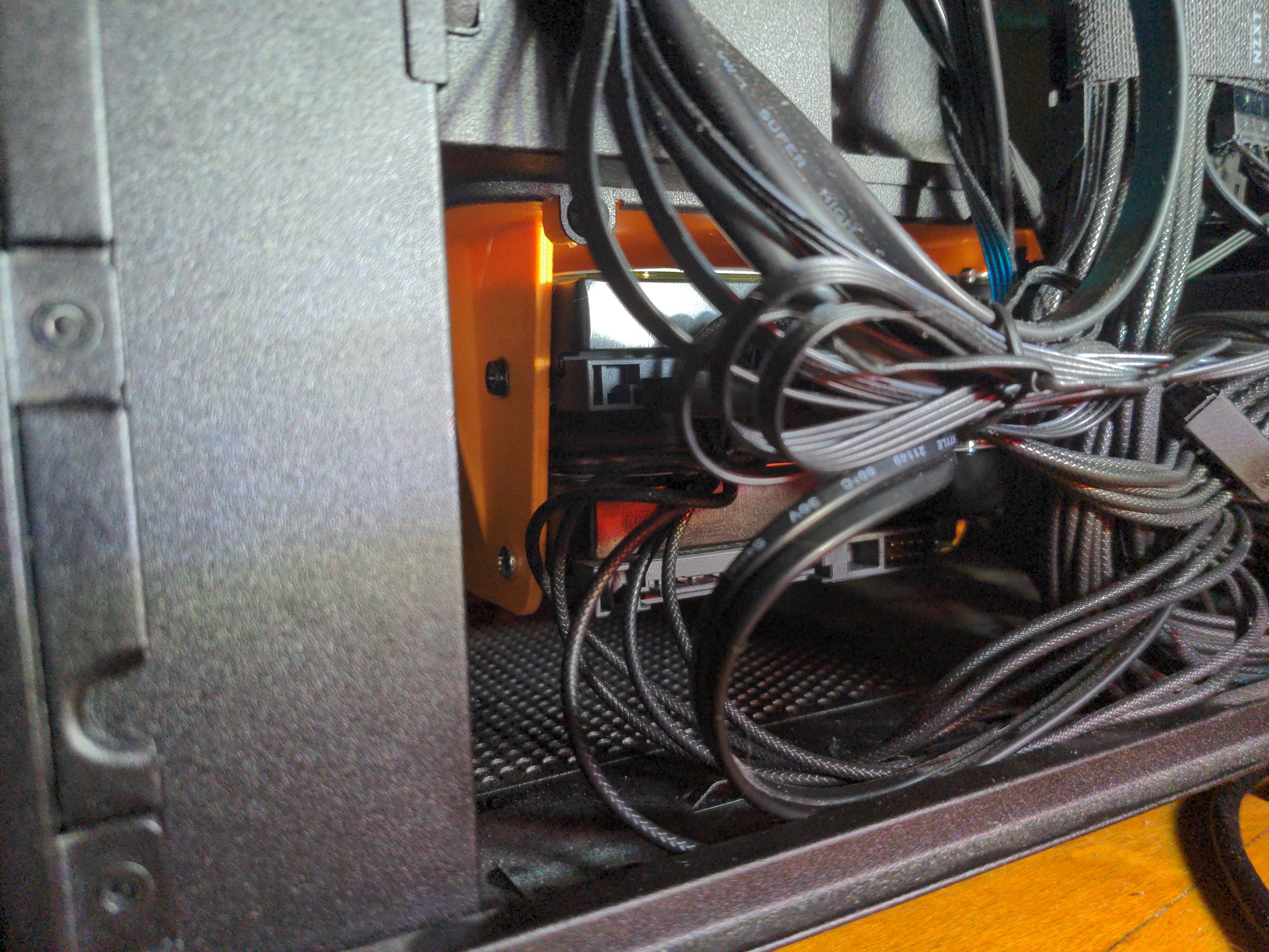
Designed in FreeCAD and printed on a custom Ender-3 V2. A couple more details / photos in the Mastodon thread.
FreeCAD mentioned!!!

edit: any chance you'd share the freecad files? I'm always curious about other people's workflows, because mine is basic if still usable. Shit has a lot of tools but a lot of them interact confusingly or can't be used together
You can grab the file here: https://matapacos.dog/stuff/h5_drive_rack3.FCStd
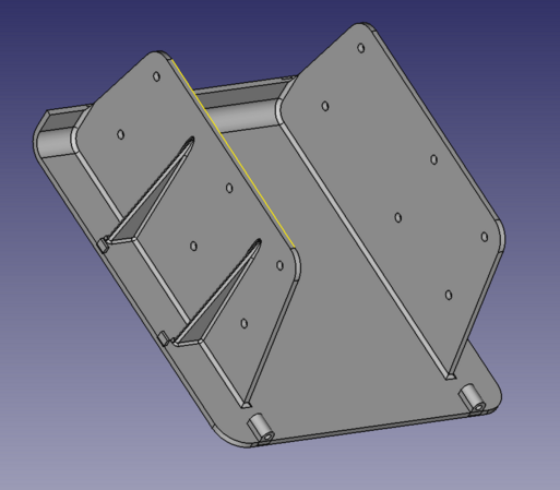
This part was designed for the NZXT H5 Flow PC case. I used vanilla FreeCAD 0.21.2 (built from source on Gentoo though). I did everything using a single solid in the PartDesign workbench. Overall, the model isn't a testament to great design, but I used datum planes as references for a lot of important bits which helps keep things a little bit more stable. I barely named any of the features though and the fillets, as always, are a crapshoot. I tried to apply them to the most structurally useful intersections and stopped when I began facing diminishing returns.
The model only tells half of the story though. There are a lot of random dimensions shoved in there, taken either by reverse-engineering the original part with a set of calipers, or by looking up prints for SATA hard drive screw locations, which are not annotated whatsoever in the model (I don't know if there is a way to do this, but it would be really useful, like adding comments to a piece of code). When you see odd random numbers thrown around, assume it was some inch measurement, plus the high limit tolerance, then converted into millimeters. Some of these measurements aren't in obvious places like a sketch, but can be found in the offsets of various pad operations, datum plane locations, or linear pattern operations. Other dimensions (particularly, internal diameters) are fudged and over-sized due to the tendency of these features to shrink by 0.2-0.4mm in the FDM 3D printing process.
Thank you!
Mostly stuff I'm familiar with, but I'm not very comfortable with Linear pattern, multi transform, and I've never used a datum plane. Very interesting to pick apart.
it's tedious and for a part like this, pointless, but have you ever used the spreadsheet workbench to make parametric models? I've only played with it once or twice but pretty neat
it's tedious and for a part like this, pointless, but have you ever used the spreadsheet workbench to make parametric models?
Oh yeah. I love doing that. Earlier when I was grumbling about annotations, at least in the spreadsheets you can write a couple sentences about what a variable does. If I'm "engineering" something from scratch, I'll typically put important dimensions and clearances in a spreadsheet and reference them within sketches. You need to be extra diligent when designing your model that it will successfully recompute given a range of values though. In the case of reverse-engineering, like this model, you throw design intent out the window and just pray everything fits.
Datum planes (as well as datum axes and points) are VERY useful. They are defined independently of any geometry in the model, and form a solid foundation to build other features from (i.e. a plane to sketch on, or an axis to bore a hole through or revolve around). You can also reference them in sketches just like any other part geometry, but they will ALWAYS be there when you change a dimension and recompute, unlike an arbitrary edge or vertex of a body. They are the canonical method to avoid the "topological naming problem." Even in commercial CAD systems like Creo Parametric or SolidWorks, which are somewhat smarter than FreeCAD about recomputing your model after changes, you WILL have problems if you're building a house of cards out of ephemeral geometry references on top of ephemeral geometry references.
Probably the most useful case for a datum plane, aside from a surface to sketch on, is a reference to perform a mirror operation. If you need to mirror a feature across a plane which isn't your base XY/YZ/XZ plane, you create a datum plane and mirror across that. Same goes for a datum axis. If you need to do a revolve operation or a radial pattern around an arbitrary axis other than X, Y, or Z, you create a datum axis and use that. These datums can also be referenced during a pad/pocket operation, where instead of specifying a dimension, you can tell the operation to pad/pocket until it hits a plane (which can be arbitrary and does not need to be parallel to the plane you are padding/pocketing from).
I've never used a multi-transform before, but all it does is combine several mirror/radial pattern/linear pattern operations into one operation. I do this to mirror features like the triangular ribs, then duplicate them at a linear offset. All a linear pattern does is duplicate geometry and translate it along an axis (i.e. turn one hole into a line of three holes). Apparently FreeCAD does not allow you to do a linear pattern of a mirror, or a mirror of a linear pattern, so these two operations need to be combined. I feel like I didn't run into this problem when I was using the RealThunder fork.
Yeah datum planes sound like the answer to my prayers tbh. Not sure how I never saw any tutorials using them in the past but that seems like it would make even moderately complex parts 10x easier. Shit really does get fragile when its references on top of references.
Thanks for the tips!
Yeah datum planes sound like the answer to my prayers tbh.
Let's not get carried away now. The computer will always find a new way to misinterpret your intent. CAD systems are like a geometric monkey's paw. :)
Anything that has vertex ordering can end up burning you. I deal with polyline geometries at work a lot and doing merge and explode operations can result in visually normal geometry with absolutely cracked vertex ordering depending on the order of the input lines.
Love to fillet two edges together and have an artifact 500 vertexes away because that's how the parts were stored internally.
Check this tutorial out if you haven't
It's using Link Branch (now officially endorsed) and is a few years old, but it goes through basically every tool in part design
I couldn't get that branch to work years ago when I first tried it and didn't care to build from scratch for how often I used it, but I do see they have appimages now. Maybe next time I'll try it. Its kinda annoying to have to go to a fork to get modern features after this many years but

It's well maintained and I've had no issues with it. There's also the Ondsel branch thats based more on LinkStage and kind of an intermediate between LinkStage and FreeCAD main.
I'd definitely try Ondsel if you haven't been able to get LinkStage working, it's definitely worth it and it's got a moderate solution to the topological naming problem as well as a much more intuitive part system. Like you can extrude and pocket faces directly.
I found a YouTube link in your comment. Here are links to the same video on alternative frontends that protect your privacy:
I've been resisting the urge to get into modeling for printing stuff, should I just start using freecad instead of blender?
IMO FreeCAD is a lot less intimidating than Blender (I have tried both). I WOULD use Blender if I were trying to make figurines and such, but if you are trying to design mechanical parts, you definitely want to use FreeCAD (or some other "solid modeling" software like SolveSpace or OpenSCAD). (...ESPECIALLY if you want to design a part to be manufactured on ANY industrial process other than 3D printing, which are precise enough physically render your .STL mesh of a sphere into the disco ball it actually describes)
They all have steep learning curves. I think at this point there are just enough tutorial videos on YouTube to get you going in FreeCAD, but the training material is scarce compared to the proprietary alternatives. But once you kind of know what you're doing, you can watch a SolidWorks/Creo/Fusion360 tutorial and kinda replicate what they're doing in FreeCAD. The basic principles are all the same, even if the user interfaces and terminology differ.
For 3D printing, you will basically live in the PartDesign workbench. The workflow is creating a 2D sketch, extruding it, then creating additional 2D sketches on various planes and extruding/pocketing them until you're done. Learning how to dimension and constrain sketches is important. The solver will not work correctly if your constraints leave any ambiguity, and the solver will ALSO not work correctly if your geometry is overconstrained. It is like solving a puzzle, figuring out how to describe the geometry unambiguously with the fewest requirements. With a little practice it becomes pretty intuitive though, and the program will tell you how many "degrees of freedom" remain after each step.
The alternate method is the Part workbench, which has a workflow more akin to classic CAD systems like AutoCAD where you create rectangular / spherical / cylindrical primitives and perform boolean operations (merge / intersection / cut / difference) to build something. While PartDesign is probably easier for most tasks, there are some things (like an exaust manifold) which are still much easier to model using the boolean methodology of the Part workbench.
This is NOT a beginner tutorial, but it covers so much that you actually get to see some complicated workflows and figure out some methodology: https://www.youtube.com/watch?v=OWNrYvxpG4k
I think it makes a lot more sense to use for functional parts than blender, yes. There might be some learning curve though, especially if you're not familiar with CAD in general
I've posted somewhere about my workflow in freecad, because they really don't give you a lot to go on when you install it, or they didn't when I started using it, but the gist is you want to use the Part Design workbench, and build up the part you want by making 2d profile sketches that you then extrude ("pad" in their terms) or revolve, etc. into a 3d shape. Then you can add giblets on or subtract voids from that first 3d object by creating more 2d sketches and using the various part design tools.
that can get you pretty far, it's like 99% of what I use, even though there's like 20 other workbenches in freeCAD
I love a customized Ender. You just keep adding bits and bobs and mods that you don't particularly need and might not even help until you have a Ship of Theseus situation where only the frame remains. Mine looked like Lain's computer nest before it finally died in a way I couldn't fix.
I gave 2 of mine away to people who wanted a printer and none of them can figure it out. It's so far off stock even I forgot half the mods I slapped on it. It also boots up with Karl Marx's face and "MEANS OF PRODUCTION" instead of the ender logo
Flashed a custom Marlin on there and had to add that