

Hello, comrades! I'm mostly not sick any more! Sorry so much for the week plus since my last post, most of the time I spent in that timespan was doing other things while I waited for components to arrive (especially because there's stuff I forgot in the first order and had to make a second one ![]() ). Components got here, I put everything together, and things... work more than they don't work
). Components got here, I put everything together, and things... work more than they don't work ![]()
What I've been up to
Behold:
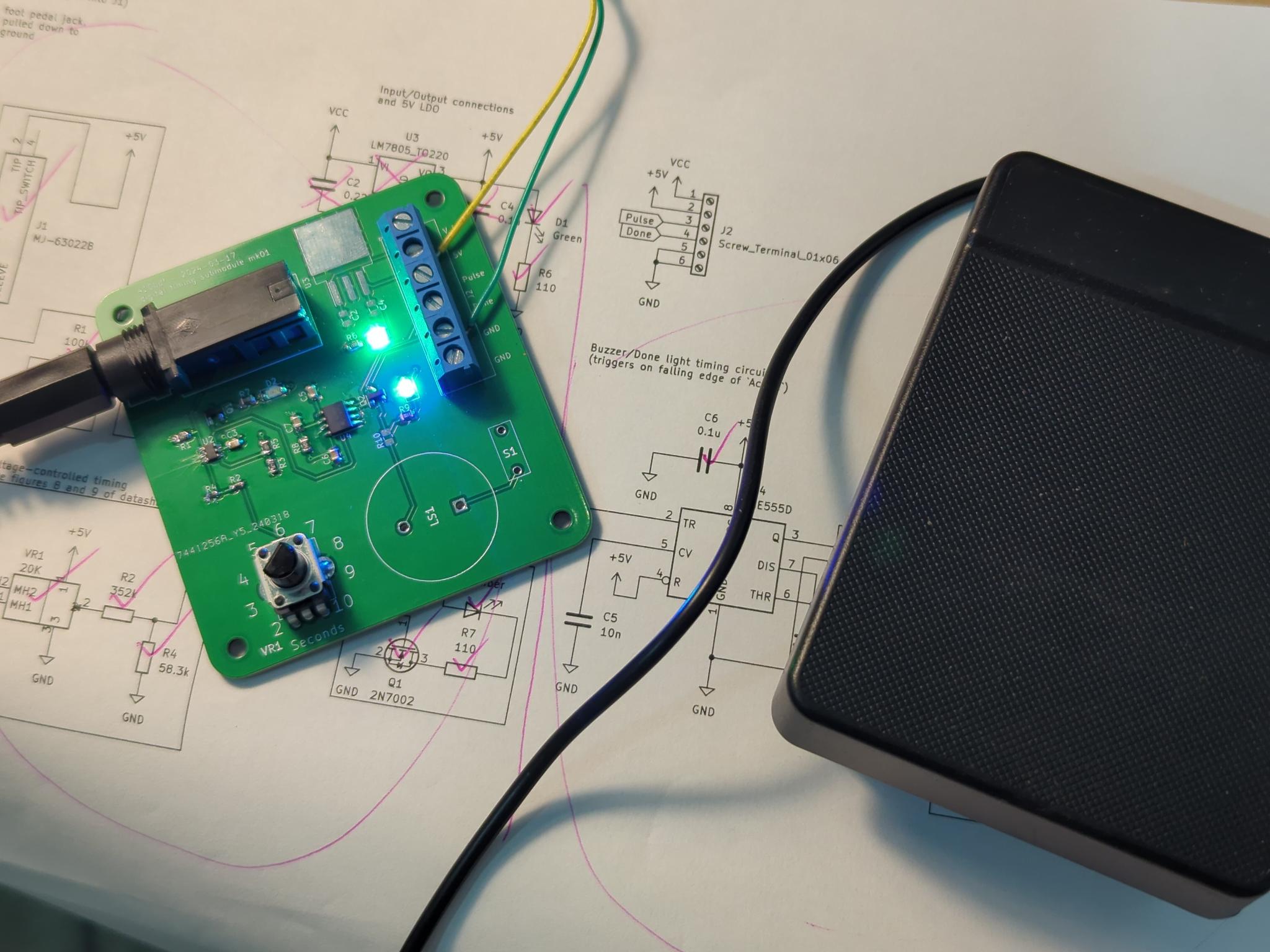

The boards are in and I made them and they work ![]()
This segment of the post is going to be dense and technical, so feel free to skim and ask questions if you feel lost and want to get caught up!
Both boards have minor bugs that I will be addressing in the next revision - the next revision being the Alpha 1 version of the Sphynx Lite. The bugs I have are as follows:
Current pump bugs:
- The knob is wired backwards. fix: make the knob go forwards, or more specifically, switch pins 1 and 3 on VR1. Ez.
- The knob doesn't have a zero offset - instead of 0.1 mA to 2 mA, it goes 0 mA to 2 mA. This is annoying; if you turn the knob all the way, the device won't do anything, you have to bump it a tiny bit. The solution is to put a resistor of roughly
115.51 kiloohms on the low-side leg of the potentiometer (exercise for the electronics-curious reader to figure out why! check the schematic from my previous post!). The wide tolerance on the potentiometer means there will be somewhat of a range on the actual minimum current, but it should be a pretty small variation, around 0.08 mA to 0.12 mA worst case variation. Since this error 1) gets stacked up with the error of the user's body being different from everyone else's, and 2) is only error on the low side, not on the high side, I'm deeming it tolerable. - Not a circuit bug per se, but I designed this around a INA350CDS, which has 50 times gain, and then I accidentally bought some INA350ABSes, which only have 20 times gain. This part is a new addition that uses R1 as a shunt for active current measurement. It works exactly as intended, just with 20 gain instead of 50 gain. This can be used for a lot of things, but particularly, an automatic shutoff of the board if the current draw ever goes above, say, 2.5 mA. More safety! However, this component has another problem, which is...
- The INA350 is fucking impossible to solder
 All these new space saving packages are absolute nightmares for hand assembly. I didn't even need space savings, it was just a cheap instrumentation amplifier that worked nice. I think I might have to ditch it because it doesn't come in a usable size. The same thing can be done with a dual opamp and some bonus resistors, which is less than $0.50 and I already have them on the board.
Digital timing bugs:
- Backwards knob again...
- Ignoring backwards knob, the range, instead of being 2 seconds to 10 seconds like I expected, is actually 2 to 7.5ish seconds. I haven't actually figured out why on this yet - I think it's because of the relatively simpler resistor divider thing I did with R2/R4/VR1, and there's some other current path I haven't thought about yet through the potentiometer. Could be something else too. In any case, the move here is probably to do something more like in figures 8 and 9 of the LTC6993 datasheet with an opamp current sink and a potentiometer, and something less like what I did, which came from the unlabeled figure on the last page of the LTC6993 datasheet. Again, one more part, but opamps are pennies and I use them elsewhere, which drives the cost down further.
- The LTC6993 is one of the microtiny packages too. This is a little worse than the other microtiny package in the INA350, in that I can just buy another inamp or an opamp for that one, but the LTC6993 is fairly unique and I can't just shop for another part that does the same thing. I'm not sure what to do about this. It's too late to add a microcontroller, but this timing issue just won't let up. I think the difficulty to solder this one might just be a thing to fix in the Lite 2. Technically, you need this level of coordination and fine motor skills to do the actual electrolysis hair removal anyways, and I was able to do it with nothing but an iron, a solder sucker, and a magnifying glass, so it's not impossible and anyone with even slightly better tools than me should be okay, but it's still a bummer. From now on, new rule, nothing smaller than a DFP package. If I get rid of the INA350 and this, then there's no more.
- The done alert doesn't work. The intention was that LED D3 turns on and buzzer LS1 beeps for half a second when the current pulse is done, alerting the operator that it's time to move to the next hair. This circuit is everything connected to U4 in the schematic in my last post. Not only did I pick the wrong kind of buzzer (very easy fix I just need to shop better), but the whole timer sticks on forever instead of just flashing on for half a second. I didn't know this at the time, but if I were to read the damn datasheet, I would have seen on page 10 that: "Monostable operation is initiated when TRIG voltage falls below the trigger threshold. Once initiated, the sequence ends only if TRIG is high for at least 10 μs before the end of the timing interval." Basically, the 555 wants to see a super quick off/on to start the timer, and I'm just giving it an off with an indefinite delay after, causing the timer to stick on. I don't really know how I'm going to handle this to be honest - my current best guess is to make some kind of quick and cheap RC high pass filter thing hooked up to a transistor that turns a high to low edge into a high to low to high pulse. I'll have to breadboard or simulate it a little bit, but if I can make this work it's a very cheap fix to the problem.
I'll be fixing this list of issues and moving both circuits to a new united design with test points and jumpers this time (thank you @macerated_baby_presidents@hexbear.net ![]() ) that will be, if it works, the first alpha version of the Lite. Progress!
) that will be, if it works, the first alpha version of the Lite. Progress!
I also cleaned up git - not sure if anyone has tried to pull down the repository and look at the boards yet, but if you have, it was broken - it should be fixed now, but you'll probably need to re-clone. If anyone tries this, let me know how it works!
New Developments
I bought a domain name! Meet sphynx.diy ![]()
Currently empty, just points to the git repo, but you have to start somewhere - this is where I want to host blog posts like this one, the assembly guide, and the usage guide and resources in the future. I'm not going to be doing much with it immediately myself, but having this makes it so we can start working on an actual site! I was thinking GitHub pages for hosting with a cute Jekyll theme, or maybe readthedocs like mentioned last time - thoughts?
Also! I used the boards above to remove a couple square centimeters of hair as a proof of concept! It's only been a couple days but I'm optimistic - I tested by tugging on the hair with tweezers, observing it tightly connected to me by the follicle, applying about 10 units of lye per Figure 2 of this very helpful resource I found, and then after current application, pulling again, for the hair to slide out with no resistance, which is a very strong indicator that it worked! Stay posted to see if they stay gone or if I need more juice, 10 units of lye is on the very low side but I'm playing it safe.
Next up
I'll absolutely be fixing up the boards as mentioned above and making and designing an Lite Alpha 1.0 next! I don't want to suggest that this one be used on human beings, but once I make it, it might be fun to buy and assemble for research purposes? Probably not, maybe best to wait until I at least make it to a beta version, but in any case I'm excited for it! It's also not too early to get work on a manual started - this is something that I'm going to try to lean on community help for.
I'm also exploring JLCPCB assembly - it would be much better for accessibility if I could keep 100% to their parts catalog (plus I wouldn't feel bad about using microtiny packages any more), and for now I think I'm close, but I know that there's at least a potentiometer I use that isn't in their catalog.
Any ways to help?
There are starting to be more things to do! I'm kinda feeling like it might be time to start pulling in folks for web stuff! If anyone has GitHub sites or Jekyll experience, getting going on a place to host an assembly guide would be awesome! This is also something that should be doable even without this particular experience if you know web stuff, so don't feel intimidated - I think this is accessible with a bit of new learning for anyone with intermediate web knowledge.
Another thing I could totally use help with is BOM management - I have links for all the parts, but I don't have them linked anywhere and I don't have them automated, tallied up based on cost, in a convenient one click buy cart, or anything else like that - if anyone likes making bills of materials in KiCAD, let me know, that would be super helpful! In a similar vein, having an audit and maybe a port of my design to 100% JLCPCB catalog compliance would be extremely nice, if either of those things sound interesting to you, let me know!
As always, stop by, hang out, say hi, ask questions, tell me what you've been up to, design review me, however you'd like to be involved is good by me! All the love and I'll talk to you in a week or so! ![]()
Tags:
@Wake@hexbear.net @raven@hexbear.net @ForgetPrimacy@lemmygrad.ml @macerated_baby_presidents@hexbear.net @sharedburdens@hexbear.net @ComradeEd@lemmygrad.ml @BountifulEggnog@hexbear.net @YearOfTheCommieDesktop@hexbear.net @Erika3sis@hexbear.net @CarbonScored@hexbear.net @frankfurt_schoolgirl@hexbear.net @oscardejarjayes@hexbear.net @crosswind@hexbear.net @lilypad@hexbear.net @OurToothbrush@lemmy.ml @tartan@lemmy.ml @AernaLingus@hexbear.net @SnAgCu@hexbear.net @naevaTheRat@lemmy.dbzer0.com @lapis@hexbear.net @proletarian_girlboss@lemmygrad.ml @Hurvitz@hexbear.net
If you'd like to be on the tag list, or if you're on the tag list and would like to be removed, let me know here!
if you know web stuff
I unfortunately have (some) web experience.
I bought a domain name! Meet sphynx.diy
Cool!
maybe readthedocs like mentioned last time - thoughts?
I think going with some Jekyll (or similar) would be a great idea. Especially if you want to do a blog.
lmao I'm right there with you, I know how to do web stuff but I'm definitely deprioritizing it because I'm having fun working on electronics and I don't wanna stop. I'll probably take on the web stuff myself eventually if nobody else is able to find the time, so don't feel obligated to help there if you're not thrilled about it, but it is on the table! There will be other ways to help too

As for Jekyll or readthedocs, I am slightly leaning towards Jekyll as opposed to readthedocs - Jekyll is a little worse at hosting a manual, but readthedocs is a lot worse at hosting a blog, and it'd be great to have them both in one place. I also know that there's a vibrant Jekyll theming and plug-in ecosystem, hopefully that's something that makes it easier to maintain a simple Jekyll static site? I do want it to look nice, I'm a sucker for nice professional looking polish and pretty graphic design, so unless readthedocs does a lot of stuff in theming and blog hosting I don't know about, Jekyll is looking like a better - although not necessarily final - pick. Still some discussion to be had though! Thoughts?
if you’re not thrilled about it
I am.
Jekyll is a little worse at hosting a manual, but readthedocs is a lot worse at hosting a blog
That's exactly my thoughts.
readthedocs does a lot of stuff in theming
There is indeed some theming to be done with readthedocs websites, but I think it all follows the same format (with a ToC in the side).
blog hosting
I mean, you can probably get it done, but more in a hacky way. It certainly isn't designed to do it.
Jekyll is looking like a better - although not necessarily final - pick
Yes. Some kind of static site generator, like Jekyll (or hugo or lektor or any of the others).
You could always have the docs and blog be separate sites and link then to each other, maybe? Something along the lines of sphynx.diy for the readthedocs instance and blog.sphynx.diy for the Jekyll blog.
I would do the opposite, make a landing page/blog/etc. on sphynx.diy and then a readthedocs on docs.sphynx.diy. But all three ways work.
Awesome work! The backwards knob is extremely relatable, I always flip connectors and symbols.
Right?? Your brain is all like "oh okay so leg 17 of this IC needs this resistor and this capacitor and leg 9 is the 5V out so it connects to this copper pour and..." and then you get to the headphone jack and it's just a headphone jack so you just wire it up, how hard could it be? A tale as old as time.
Also, hey @YearOfTheCommieDesktop@hexbear.net - Any luck with the probe/needle holder? I don't want you to feel pressured at all but if you need support or wanna send ideas/information/enthusiasm/vibes back and forth let me know!
Agh! I started writing up an update comment in the old thread like an hour ago and didn't check my notifications til now, so I put it in the wrong place! The needles and pencils I ordered have all come in now and I've done some testing!
from preliminary testing it seems like the idea of using the pencil lead collet as a holder will work! out of 6-7 pencil types tested I've come up with 2 that seem to work well for the 2 needle sizes (F and K shank)
For the larger F shank needles, I'm using this 1.1mm "Yasutomo Artist Pencil"
And for the smaller K shank needles, I'm using this 0.7mm Pentel Quicker Clicker
Both came apart reasonably easily and accommodated a small piece of wire running down the length of the pen and being soldered into the base of their brass collets, allowing for great electrical connection to the needles, and a reasonably strong physical grip. The pentel has an extremely grippy textured rubber grip, while the yasutomo is just plain plastic, but the pentel also required me to strip like 2.5 inches of insulation off the wire, since the insulation wouldn't fit down the lead tube otherwise. Both are probably usable without any further modification, through trimming the end off of the yasutomo would probably be a good idea so that the needle can engage further into the collet without disappearing down in the pen tip.
Quick notes on other pencils I tried/what else could work:
The factors I was looking at were:
- collet material. You want the part gripping the lead to be metal, ideally brass (kind of a dull gold color). Often there is a little brass sleeve, but the actual collet is just 2 pieces of plastic, which won't work. Unfortunately hard to tell this from a product listing.
- size:
- the K shank is 0.8mm so a 0.8 or 0.7mm pencil is probably what you want (0.8mm doesn't seem to even exist really)
- the F shank is 1.25mm, so a 1.1mm (used in some antique and specialty pencils) or 1.3mm (I found one for construction use)
- ease of disassembly/reassembly/ general dimensional compatibility. If its too fiddly/fragile, or won't fit a wire, has a long tip that's integral to the mechanism somehow, etc. that's ofc bad
I also looked at:
- staedtler 1.3mm jumbo construction pencil (crummy plastic collet)
- bic velocity "Side Clic" (crummy plastic collet)
- pentel Side FX 0.7 and twist-erase CLiCK 0.7 (plastic collet. hard to reassemble)
- Zebra M-301 (kinda crummy overall, removing the brass collet was tough and seemed to damage the plastic it clips into, plus the integral screw-on tip had to be cut down)
I will post pictures/instructions on how to modify the 2 I liked soon! I haven't gotten to the point of attaching any plugs or anything yet, just a wire and a continuity test. But there may be enough space for a 2.5mm aux jack at least, if that's the route we want to go.
this is fantastic work, thank you so much! Since I have the F shank needles, I'm probably going to grab a couple of the Yasutomo's and try to make myself a probe in the way you figured out - I'm currently holding on to the needle with an alligator clip which is completely a non-starter, they slip and fall out and just generally don't work at all that way. It's been fine for proof of concept but I'm excited to start testing something with a much nicer grip and a way to friction fit the needles in place!
I'm not sure where I'm at with the 2.5mm jack, I'm starting to think I might want to just go with a loose wire and a screw terminal. It feels a little more hacky and it also makes it harder to move the device around, among some other issues, but it's nice because it literally just takes wire - no other parts. Needing a screwdriver to install it is also a downside though. I'm still thinking on this one, 2.5mm jack and screw terminal are absolutely not the only two options. There has to be something available at hardware stores that's a cheap and easy fix to this - maybe a spade terminal? Possibly some kind of spring-loaded wire terminal to avoid the need for a screwdriver? Things to think about, I'd definitely love to hear your thoughts too
The yasutomo is also available from amazon/probably elsewhere btw, I just tried to link the manufacturer because they do sell it directly unlike pentel seemingly
about the jack... yeah, perhaps 2.5 mm is not the way. The nice thing about this project is that it's a single small wire to deal, so it probably won't actually end up being very important for it be able to rotate freely like an audio jack. The easy/janky fix might be lever nuts. They provide a really solid tool-less connection. But they are kinda bulky and would have to either be attached to the pencil somehow or just hanging loose at the end of the probe...
Maybe a bullet connector? They are widely available, at least in the US, might fit inside the body of the pencil with a bit of effort, or if it doesn't fit, at worst you could still have the plug side of one permanently attached to the pencil and the socket side on the wire coming from the board. They won't spin freely but that almost certainly doesn't much matter. I could try it out this week.
As far as tool requirements, what I'm doing with the pencil collets already uses a soldering iron, so the same iron could be used to do these connectors if someone doesn't have a crimper (though many wire strippers have them built in).
If someone doesn't have and can't borrow a soldering iron idk. They could use a db9 crimp and a pliers and just glue it into the tip of any pencil or pen?
Here's some photos of what I've got so far:
Show
F Shank:
Show Show
Show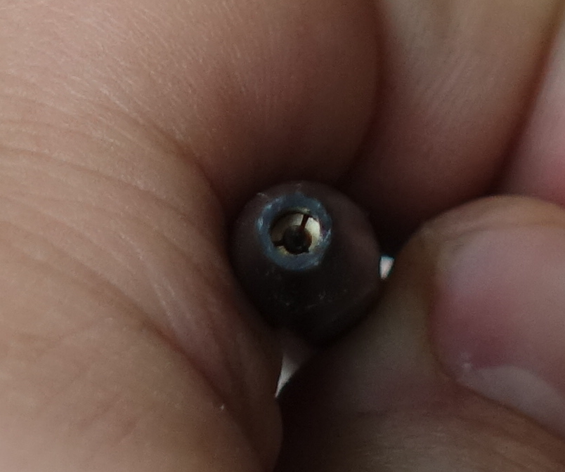 Show
Show
K Shank:
Show Show
Show Show
Show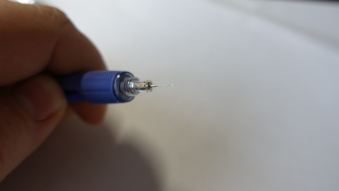 Show
Show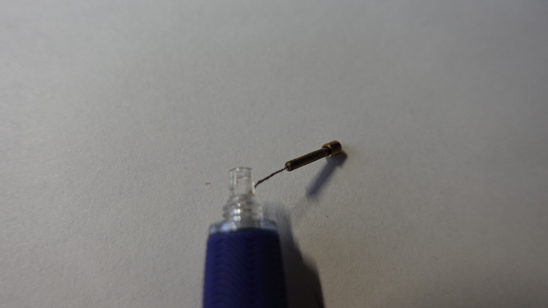
Sorry I didn't do that electrical review I promised, I've had a busy week 😅
I assume you're using lots of flux, maybe doing that fancy mini-wave technique? Hate to say it but the next step is probably hot air and paste.
Digikey has a cart sharing function. Ideally you'd get assembly through JLC and you'll be the only person ever to build one by hand. But that's tough if JLCPCB doesn't have the right type of pot.
RC filter sounds reasonable. I'm sure there's a chip meant specifically to trigger on falling edges (this is probably common digital logic thing) but then you'll have to learn how it works. Other tools in your toolbox are flip flops and digital logic gates. You could do, e.g.
AND(NOT(output), NOT(NOT(output))), so that you would get a brief pulse while the output was low and had recently been high (stacking NOT delays, translate to XOR/NAND to reduce parts count). And flip flops might tolerate the output as a very irregular clock. Bunch of related Stack Exchange questions with cute Logisim pics.No worries on electrical review, stop in and review what you feel like when you feel like
Right now it's rosin-core lead solder and a needle tip soldering iron and no other tools.

You're right about electronics stack exchange, I found a good option there - this is more or less what I had in mind, it lets me use one of my 2N7002s as a NOT gate and the resistors and capacitors are things I can reuse from other BOM entries. Depending on the internal diode on the 2N7002, I may even be able to avoid sourcing that additional diode, but having to add only a single passive component to fix this problem is pretty good.
oh jeez PLEASE get some flux paste and a little brush, it's cheap and makes surface mount so much easier. If you use an obscene amount of flux surface tension will help split the solder between the legs, rosin core doesn't have enough
schematic lgtm but analog is not my strong suit so doesn't count for much
I ended up picking a different solution, just gonna buy a dual NOT and do the top part of the circuit specified here:
https://www.edaboard.com/threads/rising-falling-edge-detector-with-positive-output-pulse.296579/post-1269830
I was able to simulate it and it worked great, plus I can recycle a capacitor and a resistor with good values from elsewhere in the schematic so I'm really only adding one IC that's under 50 cents.
start pulling in folks for web stuff!
hello it me, a web stuff girlie*, what up?
Awesome work! The 555 timer goof is a bit funny :P shit like that always happens in projects.
Unfortunately a few things have happened and I am suddenly very busy caring for a doggy with a necrotic surgery site, so I can't offer help atm. Keen to see the updates though!
I haven't looked into it at all, but I know sourcehut has a pages feature that lets you deploy a website hosted by them. I havent looked into it and it might not be suitable, but since youre already using sourcehut to host the repos it might be worth checking out.
I must admit Im a sucker for basic PDFs for A4 paper when it comes to assembly guides and manuals. I love having something printed that I can bind and leaf through. Perhaps considering a documentation format that can be published to multiple formats would be nice? I have used org mode to publish to both web and pdf (via latex) before, and the syntax tends to be unobtrusive enough that people who arent familiar with it can understand it with relative ease, but theres certainly other formats that would work (maybe texi? Though ive mostly used that for generating info manuals, i know theres texi to pdf and texi to html processors, though i dont know how featurful they are)
As always, youre doing amazing work and its super exciting to see this all coming together!